
The Drivetrain
1. Introduction
The drivetrain is the most important part of your robot. It determines how fast you can move, how much you can push, and how reliably you can execute your strategy. Getting the right motor setup, speed, and build quality first makes everything else easier. This section will cover the essentials to help you design a drive that is fast, strong, and consistent.
2. Power & Motors
Your V5RC robot is limited to 88W of power
- Use all 88W! Motor power is vital, and since the drivetrain is the most important part of your robot, give it as much power as possible while still leaving enough for scoring mechanisms. For most teams and seasons, a 66W drive provides a good balance.
VEX motors come in 11W and 5.5W versions. For drivetrains, you should almost always use 11W motors
- Avoid stacking many 5.5W motors instead of using fewer 11W ones. More motors = more weight, friction, and complexity.
Below are some possible configurations:
| Drive Wattage | Motors | Notes |
| 66W | 6 × 11W | Standard; fast, reliable |
| 44W | 4 × 11W | Slower; less common for competitive/experienced teams |
| 55W | Mixed (4 × 11W, 2 × 5.5W) | Rare; niche |
| 88W | 8x 11W | Rarely viable, leaving no motor power for scoring mechanisms. |
| Think |
|---|
Before deciding on motor count or drive wattage, consider:
|
3. Gear Ratios and Speed
3.1 How Gear Ratios Work
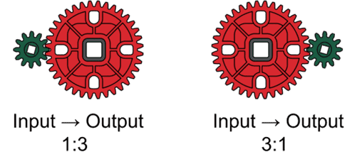
Gear ratios control the tradeoff between speed and torque in your drivetrain. The ratio is written as driving gear teeth : driven gear teeth.
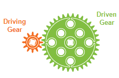
- If the driven gear is larger (fewer rotations), you get more torque, less speed.
- If the driven gear is smaller (more rotations), you get more speed, less torque.
| Example |
|---|
|
| Note |
|---|
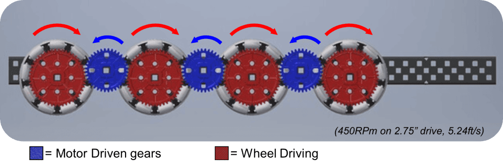
| Gear Direction: Gears can reverse rotation, so make sure all wheels on your drive spin the same way. A common solution is to alternate motor-driving gears and wheel-driving gears along the drivetrain.
|
| Resources |
|---|
| (See this resource for a deeper dive into the math behind gear ratios.) |
| Remember |
|---|
| A drivetrain that’s “too fast” overheats and stalls. A drivetrain that’s “too slow” can’t keep up in matches. |
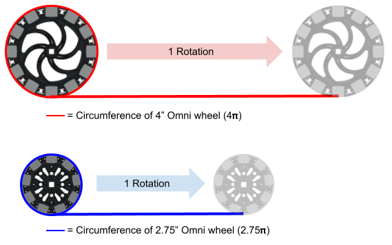
3.2 Wheel Size and Linear Speed
Wheel diameter also affects speed. Larger wheels = more distance per rotation (faster linear speed), but less torque. Smaller wheels = less distance per rotation (slower linear speed) but higher torque.
| Best Practices (Opinion) |
|---|
| Target speed for a 66W drive: 5.1–7.2 ft/s
Your drivetrain should be as fast as possible while still meeting key goals:
Why this range?
This range comes from the common competitive weight range (9–18 lbs) and the limits of what gearings are realistically achievable with VEX parts. It isn’t restrictive, it covers the full spectrum of successful drives, while filtering out extremes. |
Further Reading
Weight prediction/testing
- Test method: Build a basic drive and add weight until it matches your needs (e.g. push X lbs without overheating for a match). Record ratio of weight → speed.
- CAD method: Use a part weight spreadsheet + your test data to estimate max viable speed.
This isn’t perfect (friction varies), but it’s practical for early validation.
One Key Issue
If you CAD your whole robot before choosing a drivetrain, you risk designing around wrong speed/torque assumptions. Because the drivetrain sets the foundation (size, motor placement, gearing, layout), a bad choice can force redesigns later.
Takeaway
For most competitive robots, a 66W drive at 5.1–7.2 ft/s balances power, control, and weight. Start here, then optimize after your first tournaments.
Why this range works
It reflects the real weight of competitive robots (9–18 lbs) and the tradeoffs between overheating, driver control, and pacing. It’s broad enough for flexibility but avoids speeds that are clearly too fast or too slow.
| Resources |
|---|
|
| Important Note |
|---|
The recommended 5.1–7.2 ft/s speed range applies to 66W drives. A 44W drive is a possible alternative, but it requires a different approach:
These are all valid design considerations, but they are not the norm and should be justified. The 66W drive remains the standard for experienced teams. |
4. Chassis Layout & Dimensions
4.1 Drive Gap
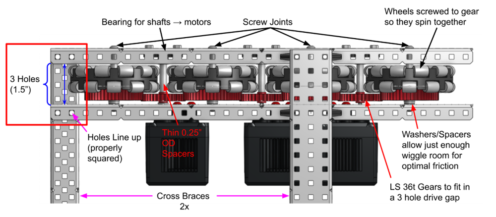
The drive gap is the spacing between the inside and outside C channels that support the wheels and gears in between.
Recommended1.5–2 inches (3–4 holes wide)
Where to add a diagram: Show CAD examples of a 1.5” vs. 2” drive gap. ImportantThe drive gap should align with C-channel holes in 0.5” increments. This ensures cross braces fit perfectly across the width of the drive, keeping the chassis square. Avoid arbitrary spacing that prevents full-width bracing. |
| Example of a drive with a 3 hole (1.5”) wide drive gap (see red rectangle) on this 450RPM 3.25” drive CAD: |
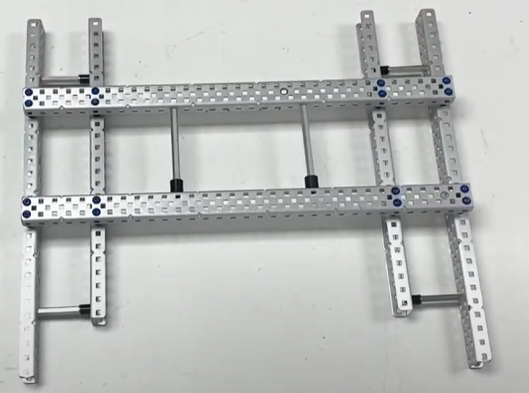
4.2 Cross Bracing & Rigidity
A drivetrain that flexes will skip gears, become un-square and lose consistency. To prevent this:
- Use at least 2 full cross braces, placed apart for maximum strength.
- Be sure to apply the Boxing building technique (see previous tab)
| Attention |
|---|
| Without bracing, your drive can twist in matches or even during assembly. Once it bends, it’s nearly impossible to fix mid-season, so add full cross braces from the start. |
| Example of a well braced chassis:
Image Credit: Harvard West Lake. (2022, July 24). 1 ChassisPart1 Video YouTube |
5. Build Practices for Reliability
Here’s how the core build concepts apply to drivetrains:
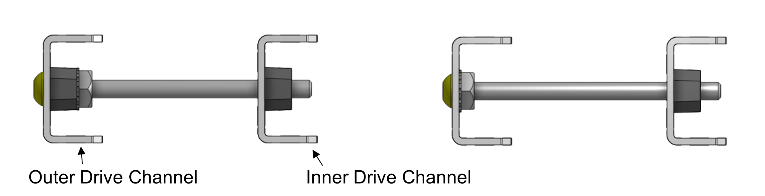
5.1 Screw joints
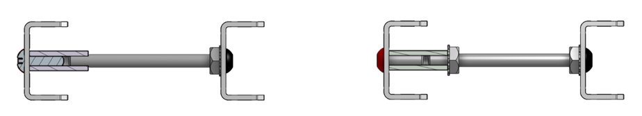
Use screw joints instead of shafts whenever possible. Shafts should only be used for gears/wheels directly powered by a motor. Shaft joints = sloppy, high-friction, and unreliable.
WATCH THIS VIDEO: VEX Build Masterclass #1 – Screw Joints
|
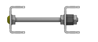
Non-Structural Screw Joint
If you have a long shoulder screw (2.25” or 2.5”), you can omit the first bearing as shown on the right image below. Both the bearing and a shoulder help center the screw to perfect spacing → improves friction.
Structural Screw Joint
Nuts are tightened on both sides of the inner channel. This way the screw joint is also a structural support, though it is heavier and harder to assemble or find room for the nuts.
Standoff Screw Joints
If the gap between your channels is larger such as on a 4 wide drive gap with ⵎⵎ orientation, you may choose to use a standoff mounted directly to the outer drive channel, and another screw threaded into it from the opposite direction. An additional Keps nut to lock the standoff in place is optional.
5.3 Squaring
Use bearings, retainers, or shoulder screws to keep your drive straight. If your drive frame isn’t square, the gears may skip under load and introduce lots of friction.
| WATCH THIS VIDEO: VEX Build Masterclass #3 – Squaring |
5.4 Misc Build Practice
Spacing
- Keep about one washer of space between components on a shaft or screw joint. Too little spacing adds friction, too much causes wobble or catching.
Gear-to-wheel connections
- Since your wheels are on screw joints, the gear beside it on the screw joint needs to directly attached to the wheel for the two to spin together
- Use at least 2 screws when attaching a gear to a wheel on a screw joint. One screw will loosen; two will stay solid. More than two adds unnecessary weight.
Bearings for Shafts
- Every shaft needs 2 points of support. If it goes into a motor, the motor counts as one bearing.
- For most drives this means bearing on outer drive channel
| Attention |
|---|
| Cutting corners here doesn’t just make the drive weaker, it makes it unpredictable. That’s the last thing you want in a match. |
6. Control & Performance Considerations
6.1 Clearance
Wheel gaps and gear placement affect barrier crossing. Large gears between wheels can hang below the chassis and catch, especially in games like Push Back. Using blue cartridges with external reductions keeps the large gear at the wheel and a smaller gear between wheels, improving clearance. Wheel count matters too: 4-wheel drives leave long exposed gear runs, while 6–8 wheel drives break them up, shielding gears and smoothing obstacle crossing.
Example: a 333RPM green-cartridge drive with large gears protruding between wheels shows poor clearance.
![]()
| If the game requires clearance, avoid oversized gears between wheels (Use blue cartridges and gear down!) and consider wheel count to minimize gear exposure. |
6.2 Cartridge Choice
Cartridge choice can directly affect drivetrain efficiency
- Friction: Cartridges closer to the motor’s native 3600 rpm have fewer internal reductions → less friction. The 600 rpm blue cartridge is lowest-friction compared to green (200 rpm) and red (100 rpm).
- Slop: Slop is the “wiggle” before the motor engages. External gearing down reduces slop, while gearing up amplifies it. Blue, usually geared down, minimises this slop. Green/red often needs gearing up, which adds play within the gearing and worsens autonomous consistency.
| Blue is usually best, it minimizes friction, reduces slop, improves clearance, and gives reliable autos. Green or red make sense only for very low rpm or packaging/materials constraints. |
6.3 Maneuverability vs. Stability
| Compact base (narrow, short wheelbase) | Wider base (larger wheelbase) |
|
|
7. Conclusion
A competitive drivetrain comes down to four main factors:
- Enough power – Typically 44–66W, most often 6 × 11W motors.
- Balanced speed – Target linear speeds of 5.1–7.2 ft/s for typical robot weights with a 66W drive.
- Strong, rigid construction with minimized friction – Screw joints, cross braces, and proper squaring ensure durability and consistent performance.
- Challenge-specific considerations – adjust your drivetrain for game-specific factors like clearance over barriers or fitting key game objects.
- EX: Clearance to go over the barrier in push back and space to fit a mobile goal in high stakes